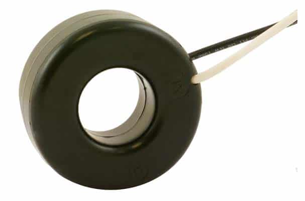
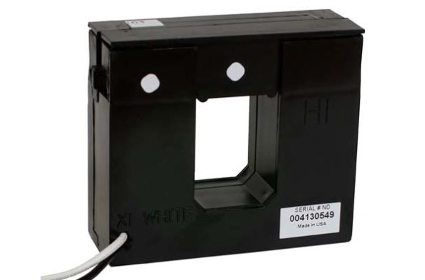
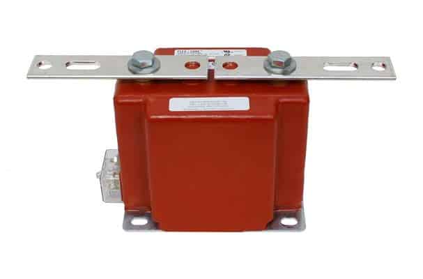
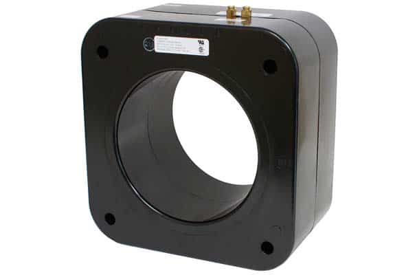
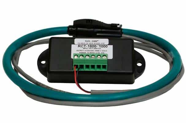
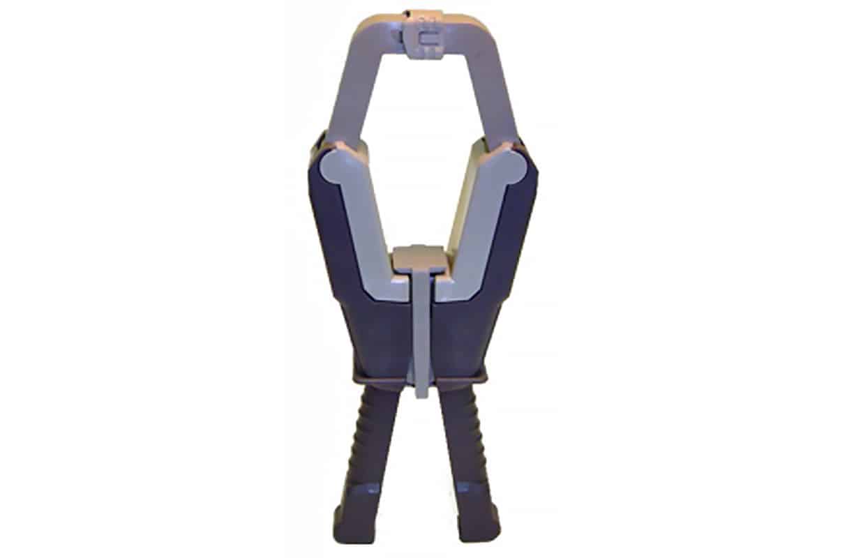
FLEX-CORE® maintains a large in-stock inventory of Current Transformers to meet your needs.
Our extensive range of 1-5A and 0.333-1V Current Transformers (CTs) ensures you will find the ideal solution for your specific application. We offer a comprehensive inventory, including Split-Core, Solid-Core, Low Voltage, Medium Voltage, Clamp-On, and Rogowski Coil CTs, all designed for a variety of common applications.
For pricing and availability on any of our Current Transformers, please contact us at (614) 889-6152 or request a quote. You can also engage in a live chat with one of our knowledgeable sales representatives by clicking the live chat tool in the lower right corner of any page.
We offer same-day shipping on most Current Transformers when orders are placed before 1:00 PM Eastern Time, ensuring fast delivery to meet your needs.
Wire Size Calculator
The Flex-Core Wire Size Calculator is used to determine the proper gauge of wire for your application.
CT Burden Chart
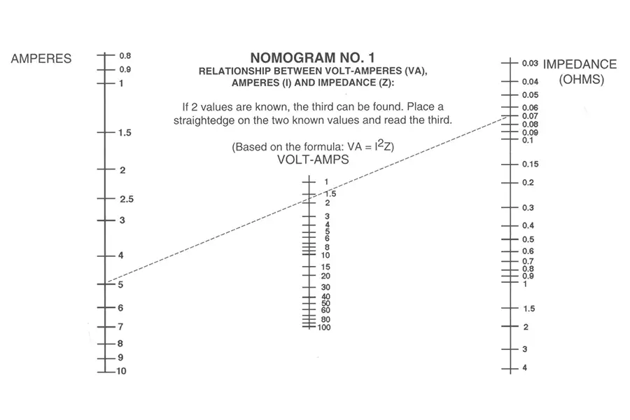
Use our CT Burden Chart to help select the appropriate current transformer to ensure your CT can handle the load without exceeding its accuracy limit.
How to Wire a Current Transformer
Learn how to properly wire your current transformer to your power source and meter.
Shop Current Transformers by Type
Designed for easy installation over existing bus or wire conductors without interrupting the circuit.
The preferred choice for new installations when there is no concern of disrupting the circuit.
Rated for applications requiring a primary current up to 600V (ANSI/IEEE) or 720V (IEC).
Zero sequence current is monitored using a core balance approach, where all three phases of a three-phase system are passed through a single current transformer.
Less power loss compared to traditional CTs, provides greater energy savings, and reduces lifecycle costs.
What is the Primary Function of a Current Transfomer?
The primary function of a Current Transformer (CT) is to measure alternating current (AC) by reducing high current levels to a lower, more manageable value for metering, protection, and control systems. CTs are used to accurately measure high currents in electrical power systems and convert them to a standardized low-level current, usually 5A or 1A, which can be safely handled by instruments and relays.
Key current transformer functions include:
- Metering: CTs allow for accurate current measurement in circuits where the current is too high to be directly measured by standard meters.
- Protection: CTs are used in protective relays to detect abnormal conditions, such as overcurrent or short circuits, and initiate appropriate protective actions.
- Isolation: CTs provide electrical isolation between high-voltage power circuits and low-voltage measuring equipment, ensuring safety.
Current Transformers Library
Explore a variety of articles and whitepapers to discover advice, strategies, and techniques for incorporating current transformers into your applications effectively. If you need assistance determining which current transformers will work for your specific application, please contact sales.
Need help understanding technical terms - reference our glossary of terms.
- Save Time and Money with Low Voltage Current Transformers on Medium Voltage Systems
- Detect Ground Faults with Zero Sequence Current Transformers
- Measuring Motor Load Current with a Current Transformer
- Using a Revenue Grade Current Transformer for Utility Tariff Metering
- Detect High Voltage in Open Circuit Current Transformers
- Energy Metering Using Potential and Current Transformers
- Solar Energy Monitoring with Voltage & Current Transformers
- Using Current & Voltage Transformers in Data Center Design & Management
- Prevent Polarity Reversal in Current Transformers
- Don't Reverse the Polarity: A Guide to Wiring FLEX-CORE® Current Transformers
- The FCL Flexible Split-Core Current Transformer offers true Current to Current Transformation Ratios
- Top 4 Mission Critical Sectors Aided by the Model# FCL Flexible Split-Core Current Transformer
- Troubleshooting Power Metering Applications - Check Your CT & PT Connections
Current Transformers - Frequently Asked Questions
Current transformers are an electrical device that safely and accurately measures electrical current in power systems and circuits. It operates on the principle of electromagnetic induction, reducing high primary currents to proportional, lower secondary currents. CTs provide:
- Electrical isolation between the primary (high-current) and secondary (low-current) circuits, making them essential for tasks like metering energy consumption.
- Protective relaying.
- Monitoring current in industrial processes.
They ensure equipment and personnel safety while delivering precise current measurements, serving as a fundamental tool in electrical engineering and power distribution.
Current Transformers work based on the principle of electromagnetic induction and consist of a primary winding, typically a single turn or a few turns of a conductor, and a secondary winding, with many more turns, wound around a magnetic core.
When an alternating current (AC) flows through the primary winding, it generates a magnetic field in the core. This magnetic field induces a proportional voltage in the secondary winding, which can be measured using instruments or protective relays. The fundamental principle is that the CT steps down the current, making it safe and convenient to measure while maintaining a proportional relationship between the primary and secondary currents, allowing for precise current measurements and protective actions in electrical systems.
No, standard current transformers (CTs) designed for measuring alternating current (AC) cannot be used for direct current (DC) measurements. CTs operate based on the principle of electromagnetic induction, which relies on the changing magnetic field produced by AC currents to induce voltage in the secondary winding. In contrast, DC currents generate a constant magnetic field that does not change in direction or magnitude. As a result, a standard AC CT cannot accurately measure DC currents since there is no changing magnetic field to induce voltage in the secondary winding. To measure DC currents accurately, specialized DC current transducers (DCCTs) are used, designed with different core materials and construction to work effectively with constant DC currents.
In a current transformer (CT), the primary current flows through the primary circuit, typically a conductor or power line passed through the CT’s core. The primary current is the current that needs to be measured or monitored. CTs are designed to step down this primary current to a proportional, reduced secondary current. The secondary current is the output of the CT, and its magnitude is directly proportional to the primary current, as determined by the CT’s transformation ratio. This step-down process ensures that the secondary current is safe and manageable for measurement or use in various applications, such as metering, protective relaying, and control systems.
The specific choice of current transformers depends on the application’s requirements, including current magnitude, accuracy, installation constraints, and environmental conditions. Selecting the correct type of CT is crucial to ensure accurate current measurement and protection in electrical systems.
Wound Current Transformers
These are the most common types of CTs. They consist of a primary winding, a secondary winding, and a magnetic core. The primary winding is connected in series with the circuit carrying the primary current to be measured. Wound Current Transformers are versatile and widely used in various applications, including metering and protective relaying.
Bar-Type Current Transformers
Bar-type CTs consist of a solid metal bar, usually made of copper or aluminum, with a secondary winding wrapped around it. They are often used in high-current applications and are known for their robust construction and reliability.
Bushings or Window-Type Current Transformers
These CTs are designed to be installed on high-voltage equipment, such as transformers and circuit breakers. They have a hole or window through which the primary conductor is passed, making them suitable for retrofitting existing equipment without interrupting power flow.
Resin-Cast Current Transformers
Resin-cast CTs have their windings encapsulated in epoxy resin, protecting against environmental factors like moisture and dust. They are commonly used in outdoor and high-voltage applications where durability and reliability are crucial.
Low-VA (Volt-Ampere) CTs
These current transformers are designed for applications where a low burden (connected load) is required, such as protection relays. They have a high turn ratio to provide a small secondary current, reducing the burden on the measuring device.
Split-Core Current Transformers
Split-core current transformers have a hinged design, allowing them to be easily installed around existing conductors without disconnecting the circuit. They are commonly used in retrofit and maintenance applications.
Zero-Sequence Current Transformers
Also known as ground CTs, these are used to measure zero-sequence currents in three-phase power systems. They are crucial for ground fault protection and detecting imbalances in the system.
Summation CTs
These CTs are used to sum the currents from multiple primary conductors into a single secondary winding. They are often used in applications where the total current of several parallel conductors need to be measured accurately.
Protection CTs
Designed for protecting relaying applications, where fast and precise detection of overcurrent and fault conditions is essential. These current transformers meet strict accuracy and performance standards.
High-Frequency Current Transformers
Designed to accurately measure high-frequency currents, often encountered in power electronics and high-frequency applications.

